7 Pin Trailer Connector Diagram : Trailer Wiring Diagram 6 Pin - Wiring Diagram And Schematic Diagram Images. Pin 1 on that connector is the trailer brakes signal. I'm working with a 15 xlt sport with the tow package and cannot get the trailer charge circuit working on the 7 pin connector. Pin 5 is designed for the trailer battery charge. Please see the trailer wiring diagram and connector application chart below. Does anyone out there have the diagram of the trailer wiring on 2001 rr 4.6hse (us version) that has hella european 7 pin connector?
12 pin trailer waiting diagram. Instead, begin by checking the connection at the trailer cord plug and outlet. A 4 pin connector is almost always used on trailers that do not utilize electric trailer brakes nor have any need for accessory power and therefore the trailer only. 5 way trailer wiring diagram allows basic hookup of the trailer and allows using 3 main lighting functions and 1 extra function that depends on the vehicle Looking at trailer wiring harness diagrams, i see that a seven.
How To Wire A 7 Way Plug On A Truck from www.chanish.org Here is the ford diagram, taken from the 99 f150 evtm 5 way trailer wiring diagram allows basic hookup of the trailer and allows using 3 main lighting functions and 1 extra function that depends on the vehicle Automotive if the $56 gets you a wiring diagram maybe, if not $14 gets. Pin 5 is designed for the trailer battery charge. A 4 pin connector is almost always used on trailers that do not utilize electric trailer brakes nor have any need for accessory power and therefore the trailer only. A number of iso standards cover trailer connectors, the electrical connectors between vehicles and the trailers they tow that provide a means of control for the trailers. Any vehicle towing a trailer requires trailer connector wiring to safely connect the taillights, turn signals, brake lights and other necessary electrical systems. I'm working with a 15 xlt sport with the tow package and cannot get the trailer charge circuit working on the 7 pin connector.
Note, the trailer wiring from c125 and c150 onwards doesn't seem to make a lot of sense to me, unless the pin arrangement on the.
Does anyone out there have the diagram of the trailer wiring on 2001 rr 4.6hse (us version) that has hella european 7 pin connector? This is the style we recommend. 4 pin 7 pin trailer wiring diagram light plug | house electrical wiring diagram. How to install and connect a trailer brake controller. A 4 pin connector is almost always used on trailers that do not utilize electric trailer brakes nor have any need for accessory power and therefore the trailer only. This type of connector is normally found on utvs, atvs and trailers that do not have their own braking system. A number of iso standards cover trailer connectors, the electrical connectors between vehicles and the trailers they tow that provide a means of control for the trailers. Wiring a 12 volt charge wire to the 7 pin connector when an after market brake controller is used. If you have a round connector, commiserations. Trailer 7 pin plug how to test. These are listed below, with notes on significant deviations from them that can cause problems. Please see the trailer wiring diagram and connector application chart below. Automotive if the $56 gets you a wiring diagram maybe, if not $14 gets.
Trailer 7 pin plug how to test. This type of connector is normally found on utvs, atvs and trailers that do not have their own braking system. On the 14 and older trucks a relay and fuse came with the truck that needed to be installed to get the charge circuit. Any vehicle towing a trailer requires trailer connector wiring to safely connect the taillights, turn signals, brake lights and other necessary electrical systems. I put this here because i had a hard time finding and figuring this out for my trailers.
Phillips 7 Way Trailer Plug Wiring Diagram | Free Wiring Diagram from ricardolevinsmorales.com This 2003 silverado trailer wiring diagram model is far more appropriate for sophisticated trailers and rvs. 5 way trailer wiring diagram allows basic hookup of the trailer and allows using 3 main lighting functions and 1 extra function that depends on the vehicle Automotive if the $56 gets you a wiring diagram maybe, if not $14 gets. Please see the trailer wiring diagram and connector application chart below. Trailer 7 pin plug how to test. Does anyone out there have the diagram of the trailer wiring on 2001 rr 4.6hse (us version) that has hella european 7 pin connector? The below information is for reference and is commonly used throughout the various styles of connectors are available with four to seven pins to allow transfer of power for the lighting as well as auxiliary functions such as electric. I was adding an extra 4 pin connector behind the back bumper, so i could plug in my aftermarket led blinker/stop/tail light strip, and not have to unplug it when i plug in my 4 pin trailer i drew this crude diagram to help explain.
The 7 pin plug (truck side) is available with the pig tail set up that plugs. Does anyone out there have the diagram of the trailer wiring on 2001 rr 4.6hse (us version) that has hella european 7 pin connector? I was adding an extra 4 pin connector behind the back bumper, so i could plug in my aftermarket led blinker/stop/tail light strip, and not have to unplug it when i plug in my 4 pin trailer i drew this crude diagram to help explain. Automotive if the $56 gets you a wiring diagram maybe, if not $14 gets. The seven pin connector has pin assignments as follows. Trailer 7 pin plug how to test. I'm working with a 15 xlt sport with the tow package and cannot get the trailer charge circuit working on the 7 pin connector. European spring trailer electrical cable 7 pin trailer connector. This 2003 silverado trailer wiring diagram model is far more appropriate for sophisticated trailers and rvs. 7 pin 'n' type trailer plug wiring diagram7 pin trailer wiring diagramthe 7 pin n type plug and socket is still the most common connector for towing. 4 pin 7 pin trailer wiring diagram light plug | house electrical wiring diagram. If anyone needs it, the diagram is attached: # color gage circuit function 1 white 10 common ground 2 blue 12 electric brake 3 green 14 on alot of the trailer plug kits, they have pics and diagrams in the package.
I'm working with a 15 xlt sport with the tow package and cannot get the trailer charge circuit working on the 7 pin connector. The color of the wires are brown, black, green, white, red, blue and yellow (all are solid color no stripe. I was adding an extra 4 pin connector behind the back bumper, so i could plug in my aftermarket led blinker/stop/tail light strip, and not have to unplug it when i plug in my 4 pin trailer i drew this crude diagram to help explain. These are listed below, with notes on significant deviations from them that can cause problems. Pin 1 on that connector is the trailer brakes signal.
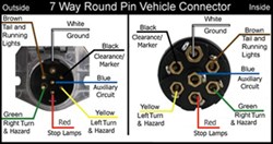
Wiring Diagram for 7-Way Round Pin Trailer and Vehicle Side Connectors | etrailer.com from www.etrailer.com I hope this helps some folks, because it's pretty tough finding this online. How to install and connect a trailer brake controller. Pin 1 on that connector is the trailer brakes signal. Wiring a 12 volt charge wire to the 7 pin connector when an after market brake controller is used. The seven pin connector has pin assignments as follows. This is the style we recommend. Instead, begin by checking the connection at the trailer cord plug and outlet. This 2003 silverado trailer wiring diagram model is far more appropriate for sophisticated trailers and rvs.
Ebs (electronic brake system) connectors are used for the electrical connection of the abs/ebs braking systems between the truck and trailer for both 12v and 24v electrical systems.
7 pin 'n' type trailer plug wiring diagram 7 pin trailer wiring diagram the 7 pin n type plug and socket is still the most common. Automotive if the $56 gets you a wiring diagram maybe, if not $14 gets. I'm working with a 15 xlt sport with the tow package and cannot get the trailer charge circuit working on the 7 pin connector. European spring trailer electrical cable 7 pin trailer connector. 4 pin trailer wiring diagram. Ebs (electronic brake system) connectors are used for the electrical connection of the abs/ebs braking systems between the truck and trailer for both 12v and 24v electrical systems. Check out or trailer wiring diagrams for a quick reference on trailer wiring. Trailer connector pinout diagrams 4 6 7 pin connectors. I was adding an extra 4 pin connector behind the back bumper, so i could plug in my aftermarket led blinker/stop/tail light strip, and not have to unplug it when i plug in my 4 pin trailer i drew this crude diagram to help explain. Does anyone out there have the diagram of the trailer wiring on 2001 rr 4.6hse (us version) that has hella european 7 pin connector? Trailer 7 pin plug how to test. 5 way trailer wiring diagram allows basic hookup of the trailer and allows using 3 main lighting functions and 1 extra function that depends on the vehicle The 7 pin plug (truck side) is available with the pig tail set up that plugs.
Share :
Post a Comment
for "7 Pin Trailer Connector Diagram : Trailer Wiring Diagram 6 Pin - Wiring Diagram And Schematic Diagram Images"


Post a Comment for "7 Pin Trailer Connector Diagram : Trailer Wiring Diagram 6 Pin - Wiring Diagram And Schematic Diagram Images"